Simple structure, small size, high efficiency, long life, light weight, strong self-priming ability, it is suitable for machine tools, forging, metallurgy, engineering, mining and other machinery and other hydraulic transmission systems The pump can also...
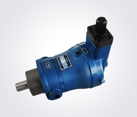
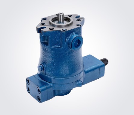
CY14 axial piston pump is an axial piston pump with oil distribution plate and rotating cylinder block. Because the hydraulic static balance structure is adopted between the sliding shoe and the variable head, and between the oil distribution pan and the cylinder block, it has the advantages of simple structure, small volume, high efficiency, long life, light weight and strong self-priming ability compared with other types of pumps. It is suitable for machine tools, forging, metallurgy, engineering, mining and other machinery and other hydraulic transmission systems. The pump can also be used as a hydraulic motor only by changing the motor oil distribution pan.
The main part (see structure profile) is driven by the drive shaft to rotate the cylinder block, so that the seven plungers evenly distributed on the cylinder block rotate around the center line of the drive shaft, and the slide shoe in the column slide assembly is pressed against the variable head (or swash plate) through the center spring. In this way, the plunger reciprocates with the rotation of the cylinder block to complete the oil absorption and oil pressure action.
Pressure compensation variable pump outlet flow with the size of the outlet pressure approximates in a certain range according to the constant power curve. When the high-pressure oil from the main part enters the lower chamber of the variable housing (d) through channels (a), (b) and (c), the oil enters channels (f) and (h) respectively through channels (e). When the force of the spring is greater than the hydraulic thrust from the oil channel (f) into the lower ring area of the servo piston, the oil passes through (h) to the upper chamber (g). Push the variable piston downward to increase the pump flow. When the hydraulic thrust on the annular area of the lower end of the servo piston is greater than the force of the spring, the servo piston moves upward, blocks the channel (h), and makes the oil in the (g) cavity relieve pressure through the (i) cavity. At this time, the variable piston moves upward, the variable head decliner decreases, and the flow rate of the pump decreases.
When adjusting the flow characteristics, you can first screw the limit screw to the top end, according to the required flow and pressure change range, adjust the spring sleeve, so that the initial pressure when the flow begins to change meets the requirements, and then screw the limit screw to the final pressure when the flow no longer changes, among which the flow and pressure change relationship is determined by the design of the pump itself.


|
Size | Type |
10(16)YCY |
25(40)YCY |
63(80)YCY |
160YCY |
250(400)YCY |
|
A |
φ 125 |
φ 150 |
φ 190 |
φ 240 |
φ 280 |
|
B(f9) |
φ 75 |
φ 100 |
φ 120 |
φ 150 |
φ 180 |
|
C |
27.5 |
32.5 |
42.8 |
59 |
63.9 |
|
D(h6) |
φ 25 |
φ 30 |
φ 40 |
φ 55 |
φ 60 |
|
E |
4 |
4 |
4 |
4 |
5 |
|
F |
30 |
45 |
50 |
100 |
100 |
|
G |
40 |
52 |
60 |
106 |
110 |
|
H |
41 |
54 |
62 |
110 |
112 |
|
I |
86 |
104 |
122 |
180 |
212 |
|
J |
109 |
134 |
157 |
230 |
272(277) |
|
K |
194 |
246 |
300 |
411 |
492(502) |
|
L |
71 |
83 |
108 |
141 |
170 |
|
M |
M14 × 1.5 |
M14 × 1.5 |
M18 × 1.5 |
M22 × 1.5 |
M22 × 1.5 |
|
N |
M10 |
M10 |
M12 |
M16 |
M20 |
|
P |
M16 |
M20 |
|||
|
Q(h9) |
8 |
8 |
12 |
16 |
18 |
|
R |
φ 100 |
φ 125 |
φ 155 |
φ 198 |
φ 230 |
|
S |
142 |
172 |
200 |
340 |
420 |
|
T |
M22 × 1.5 |
M33(M42) × 2 |
M42(M48) × 2 |
φ 55 |
φ 64( φ 66) |
|
U |
φ 64 |
φ 76 |
|||
|
X |
294 |
362 |
439 |
595 |
690(700) |
|
Y |
258 |
317 |
390 |
533 |
629(639) |
|
Z |
50 |
66 |
74 |
100 |
100 |
|
EE |
100 |
120 |
140 |
173 |
210 |
|
FF |
288 |
351 |
400 |
448 |
516 |